IEEE C37.011 - The Transient Recovery Voltage (TRV) is the voltage that appears across the terminals of a circuit breaker after a current interruption. This voltage may be considered in two successive time intervals: one during which a transient voltage exists (TRV), followed by a second during which a power-frequency voltage alone exists. Below is an example of the TRV for 145kV transmission line system. The TRV follows a transmission line fault clearance.
TRV is a consequence of different voltage response of the circuits on the source side and load side of the circuit breaker.
This difference creates the TRV across the breaker terminals.
The standards covering TRV analysis are:
The TRV appearing across a circuit breaker while it is opening will challenge the longitudinal voltage withstand of the gap between the breaker poles. If the system TRV reaches the gap withstand voltage, a longitudinal breakdown will take place. This is called a reignition if the breakdown occurs before a quarter cycle following the current interruption, and a restrike if it occurs after.
Restrikes must be avoided by design, and re-ignition minimized, as they can create hot-spots in the circuit breaker and high-frequency transients in the circuit, the worst cases being if the circuit-breaker is simply not able to interrupt the current, or if the successive breakdowns create a voltage escalation.
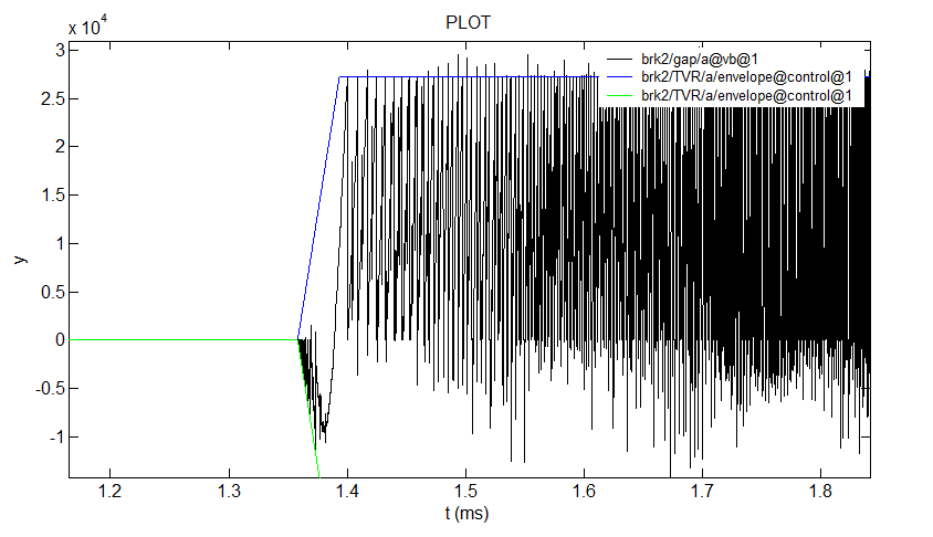
Below is an example of an unsuccessful breaker opening in a 13.8kV system, with multiple restrikes and voltage escalation.
1. System modeling: The system must be modeled for frequencies ranging from the fundamental to few kilohertz. For the most part, and especially for conductors, frequency-dependent modeling is required.
2. Simulation of worst-case scenarios: depending of the system, some clearing scenarios will be more challenging for the circuit-breaker. For example, 3-phase ungrounded faults are very often the most challenging events to clear, especially if they occur at the secondary of a series-reactor or a transformer. For lines, short-line-faults (single-phase to ground) and 3-phase terminal faults are the worst cases. The outcomes of the worst-case scenario simulations are the prospective TRVs.
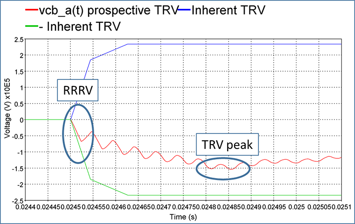
3. Comparison of the prospective TRVs (obtained by simulation) with the breaker inherent TRV (obtained in lab by standardized tests): the prospective TRV is superimposed with the breaker inherent TRV envelop which is built with 2 or 4 parameters and depends on:
Both the TRV magnitude and its initial slope (known as the Rate of Rise of Recovery Voltage or RRRV) must be inside the inherent TRV envelop, considering a safety margin.
The following figure shows a 145kV system prospective TRV obtained during the simulation of a 13kA short-line single-phase-to-ground and superimposed with a 4-parameter inherent TRV of a circuit breaker rated 30kA and which class is >100kV effectively earthed.
TRV occurs anytime a circuit-breaker interrupts a current. However, only breakers rated 3.6kV and above are concerned.
TRV studies are typically performed for the following cases:
Breakers disconnecting transmission lines: In this case, two cases are simulated:


Breakers disconnecting reactors

EMTP® is the most versatile platform for TRV analysis, with built-in standards and functionalities that allow to effortlessly compare the system prospective TRV, obtained by simulations, and the breaker inherent TRV envelope.
Here are some major advantages:
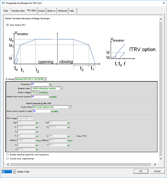
EMTP® Circuit Breaker model for TRV
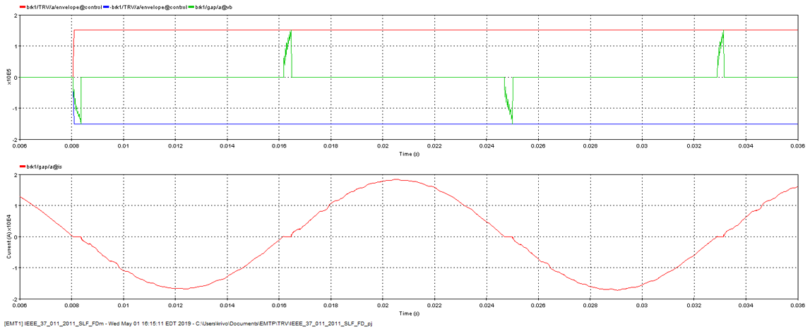
EMTP® Results for a TRV with multiple re-ignitions, including the withstand envelope/voltage and current
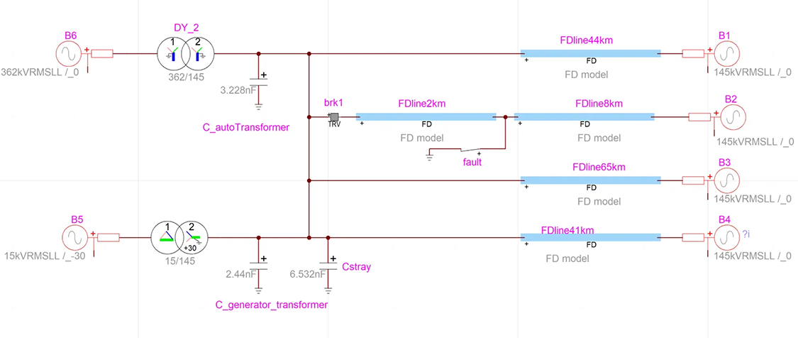
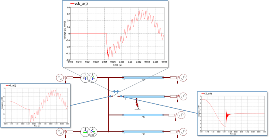
EMTP® circuit with a breaker model for TRV analysis
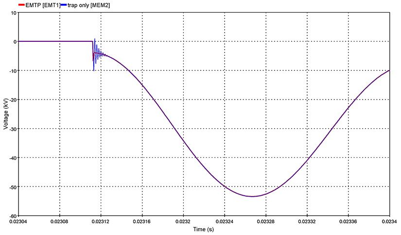
EMTP®, which also uses trapezoidal integration, solves this problem by using the backward Euler integration method during discontinuities and reduces the integration time-step when they occur.
Below is an example of the TRV results given by EMTP® compare to a solver using trapezoidal integration with numerical damping resistances.