Microgrids are relatively small systems in size but high in complexity. They can operate grid-connected or islanded. In the latter case, they do not benefit from the power and frequency support of the grid and maintaining their stability becomes a challenge due to the lack or the low inertia. Often, generation is distributed and inverter-based which forces to setup protection systems accordingly and to ensure a acceptable power quality.
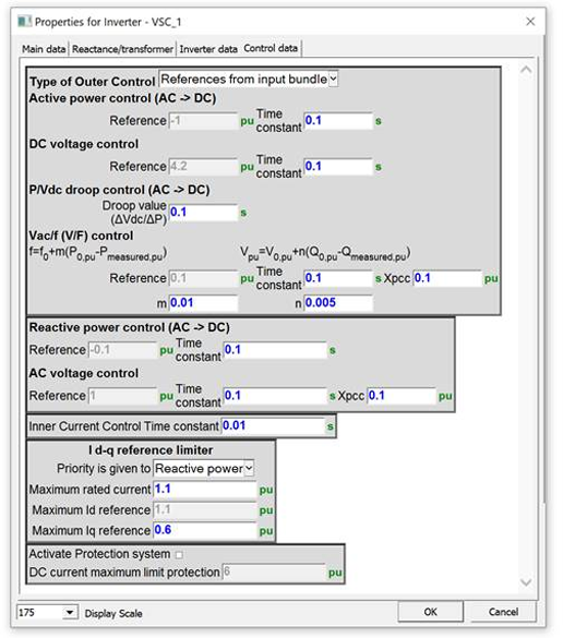
Menu of the EMTP® built-in inverter model – Control data tab
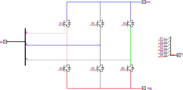
Inverters can either be modeled in detail or as an Average Value Model (AVM). Detailed models consider the PWM modulation and detailed IGBTs.
Their simulation requires small time steps. AVM replaces the inverter bridge with a 3-phase controlled voltage sources, significantly speeding up the simulation,
while remaining accurate enough for many common studies.
Detailed converter model
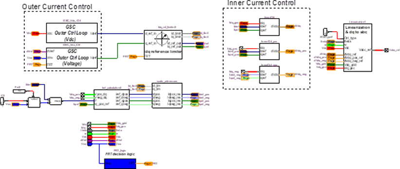
The converter control is modeled in detail with the measurement sampling and filtering, the Phase-Locked Loop (PLL), the regulation loops and the protection system.
The regulation loops are implemented in the DQ0 reference frame which allows a decoupled control of the active and reactive power. A decoupling between positive
and negative sequences can also be achieved.

EMTP® generic PLL
The control is staged with a slow loop (outer) that computes the current reference values and fast loop (inner) that generates the AC voltage references controlling
the converter.
There are four different outer loop control methods built in the EMTP® Inverter model: Active power control, VDC control, P/ VDC Droop Control and VAC/f control.
VAC/f control is used in the islanded mode with the phase angle and frequency references generated from an internal oscillator, while the ac voltage magnitude is
controlled by a PI controller.
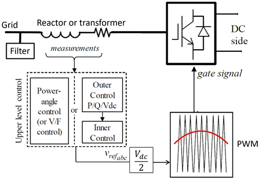
Control System diagram of a Voltage Source based Inverter
Like most models in EMTP®, the inverter is a white box accessible and customizable.
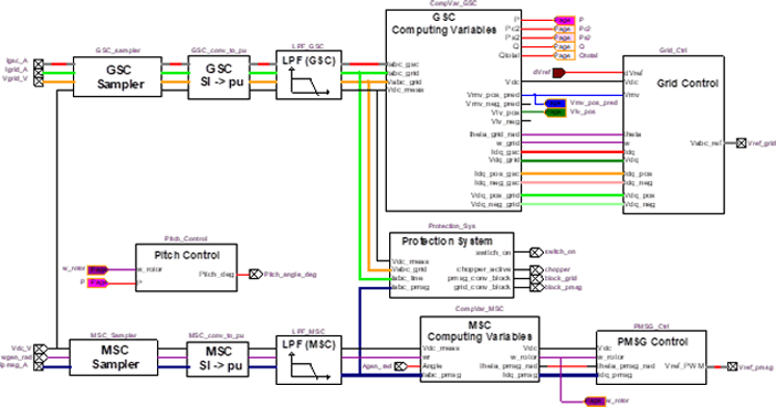
Full-converter control
Grid side controller control scheme