High Voltage Direct Current (HVDC) transmission has emerged over the past few decades as an optimal solution for energy transfer in many applications.
It exists two main HVDC converter technologies:
Modular Multilevel Converter (MMC) technology uses series-connected half-bridge modules. It has overcome many limitations of other multilevel converter topologies for HVDC applications. MMC topologies allow using a lower switching frequency to reduce converter losses. In addition, filter requirements are eliminated by using a significant number of levels per phase. Scalability to higher voltages is easily achieved and reliability is improved by increasing the number of sub-modules (SMs) per arm.
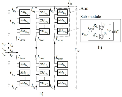
a) MMC topology b) Half-bridge converter of the i-th Sub-module
Reference:
N. Flourentzou, V. G. Agelidis and G. D. Demetriades, “VSC-Based HVDC Power Transmission Systems: An Overview,” IEEE Trans. on
Power Electronics, vol. 24, no. 3, pp. 592-602, March 2009.
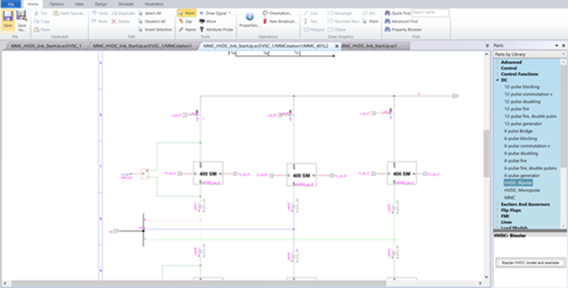
EMTP® comes with a built-in, customizable MMC station model, that comes in two configurations: Monopole and Bipolar with earth grounding return. In addition to that,
there are also pre-built LCC station models, that can be easily modified or rebuilt from scratch using EMTP® parts library.
Because these models have an open architecture, any configurations can be achieved.
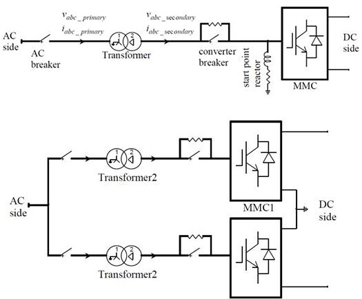
EMTP® models of a) Monopolar HVDC transmission system and b) of the connection of two MMCs on one end of the Bipolar DC link
The HVDC station models are composed of:
LCC 12-pulse converter essentially consists of two 6-pulse bridges connected in series. Each 6-pulse bridge is fed from two different windings
(one is Wye and the other is Delta connected) of a 3-winding transformer with a 30-degres phase-shift (vs 60deg in a 6-pulse bridge)
to achieve better harmonic suppression.
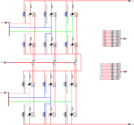
EMTP® model of 12-pulse LCC converter. Each thyristor switch is paired with an RLC snubber.
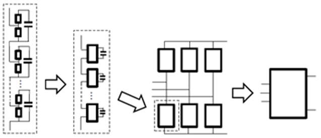
Each phase arm of the MMC model is an assembly of several Sub-Modules (SMs) in series. SMs are half-bridge converters, containing a capacitor and two IGBTs with
antiparallel diodes. Depending on the state of the IGBT switches, the SMs can either be in ON, OFF or blocking state.
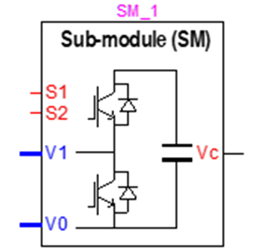
EMTP® model of an MMC Sub-Module – when switch S1 (upper) is ON and S2 is OFF, the voltage across the SM equals the capacitor voltage Vc.
When S1 is OFF and S2 is ON, the SM voltage equals zero. When both switches are OFF the SM is in the blocking state and its voltage depends on
the current direction through the arm.
Depending on the type of study and the level of accuracy required, EMTP® offers 4 different MMC models with different levels of detail.
Full detailed MMC model includes non-linear model of every IGBT and diode in each SM. This model is the most accurate and can consider every conduction mode
in the MMC. However, to accurately model simultaneous switching of multiple IGBTs, it requires a small-time step, which can be very computationally intensive.
Full detailed models are usually used for advanced studies, prototyping of different SM topologies, and validation/calibration of simplified models.
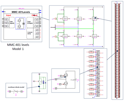
Subcircuit breakdown of the Full detailed MMC-401 Level model in EMTP®
Detailed equivalent model replaces the IGBTs and diodes by small ON state resistance and large OFF state resistance, while the capacitors are replaced by an equivalent current source. This model significantly simplifies the circuit solution, while still considering each SM separately and individual capacitor voltages.
Switching function of arm model further simplifies the model by replacing the entire MMC arm with a switching function that calculates the total arm voltage and current based upon the number of switches in the ON state. It also assumes a uniform voltage distribution among the arm capacitors to replace them by a single equivalent arm capacitor Carm=C/N, where N is the total number of SMs in the arm. Switching function of arm model doesn’t represent the individual SMs, so the balancing control of capacitor voltages cannot be studies with this model, however, higher level phenomena such as the circulating currents and conduction losses are still considered.
EMTP® MMC models ranked by the decreasing resolution, from Full detail model, over Detailed equivalent and Switching function, to Average Value Model.
The first two EMTP® models consider individual SMs, and they can be automatically set to either one of these
MMC levels: MMC-401L (400SM/arm), MMC-101L (100SM/arm) and MMC-21L (20SM/arm).
Average Value Model (AVM) based on power frequency assumes that all SM capacitor voltages are perfectly balanced and that there are no circulating currents, so that therefore internal MMC variables are perfectly controlled. Each MMC phase is represented by a controlled voltage source, and the equivalent MMC capacitance is determined. The AVM model executes very fast and it is still suitable enough for many common studies.
Two different Upper level control strategies are built in the EMTP® MMC model: Vector current control and V/F control. In V/F control, the phase angle and frequency are
generated from an internal oscillator, while the ac voltage magnitude is controlled by a PI controller. V/F control is used to connect a VSC to an AC grid with a passive load
or in wind turbine applications.
Vector current control is used by the outer loop to control active and reactive power independently in the dq frame and compute the dq current reference for the inner
loop controller. There are three different outer loop methods built in the EMTP® MMC model: Active power control, DC Voltage control, and P/Vdc Droop Control.
The inner control loop computes the reference dq voltage signals that will be used for the Lower level control.
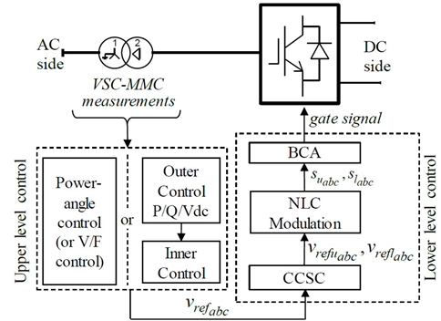
MMC Control System Diagram
Lower level control’s task is to stabilize internal MMC variables. It is composed of:
The behavior of an integrated HVDC system under different load and fault conditions will depend on the complex interaction between the converter and the AC network. To accurately evaluate performance of this highly non-linear system, the simulation must be performed in time-domain. Some of the most important time-domain studies for an HVDC system include:
EMTP® offers you a versatile simulation platform, with highly customizable devices and control libraries allowing you to assemble and analyze detailed models of
HVDC stations in a variety of operating conditions and fault scenarios.
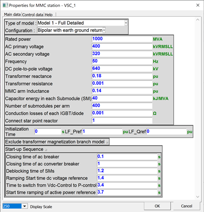
Menu of the EMTP® built-in MMC station model
The content of these models is accessible and customizable!